Zone 2A
Caretaker House
One house, two sides — this is the caretaker residence side: 3 bed / 2 bath, full kitchen, dining, living areas, and decks. Shares the same TMOD factory-built structure as the Welcome Center.
🏡 Now Recruiting — Move-In August 2027
This house is also the future home of Turkey Toe's full-time live-in caretaker. See the full role, what's included, and how to inquire.
See the Caretaker Role →Caretaker Side — What's Included
- •3 bed / 2 bath residence
- •Full kitchen, dining, and living areas
- •Decks
- •Car parking & drop-off
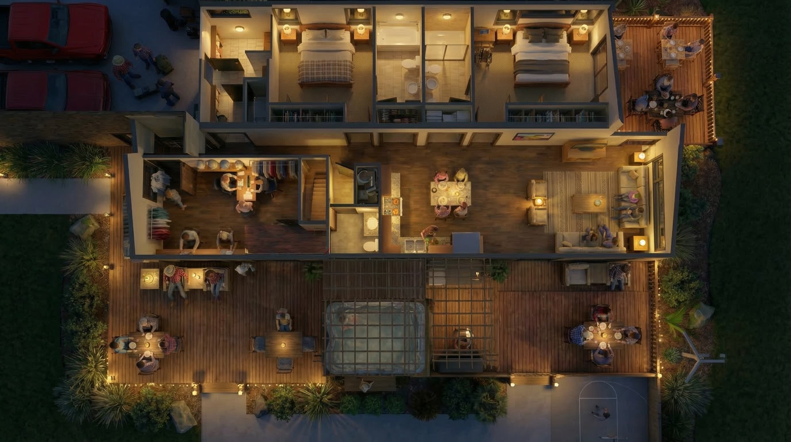
Caretaker House Floor Plan
One house, two shared-use sides — check-in & Welcome Center, plus the caretaker residence. The exact lock-off point between the private caretaker side and the shared Welcome Center wing (including the shared bathroom guests use) is flexible and will be set based on who the right caretaker partner turns out to be.
Caretaker Zone Walkthrough
Video overview of the caretaker zone development at Turkey Toe Retreat.
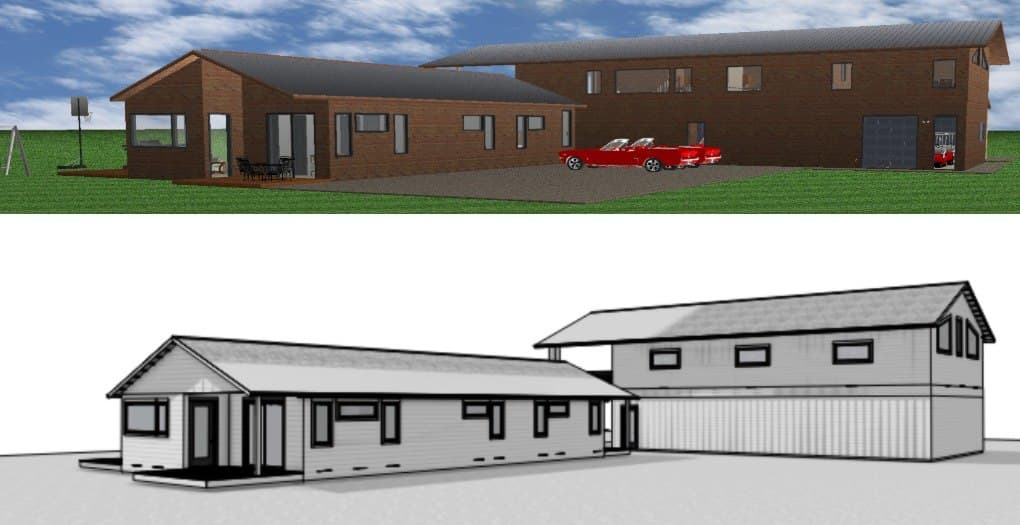
Same two buildings, viewed from the opposite corner of the site — Devon's colored CAD model on top, VIZ's matching structural sketch below. Confirms how the caretaker house (left, single-story with covered patio) and the taller Party Barn (right, with equipment bay and Roost windows above) sit aligned on the ground — two separate structures, consistent across both tools.

A third angle, square to the front — Devon's colored CAD model on top, VIZ's matching structural sketch below. Shows the garage bays at ground level, the exterior stair climbing up to The Roost deck, and the breezeway tying the Party Barn over to the caretaker house — all consistent between both tools.
New Concept — Caretaker Parking & Mud Room Access Flow
Under Structural Review · Not Yet in the CD Set
As full-time caretakers move onto the property, the Party Barn's garage bays need to work two ways: everyday caretaker parking when nothing is happening on-site, and clear space for guest/event vehicles when the venue is hosting. This concept lays out exactly how that switches back and forth, and how caretakers get from their car into the house without crossing the event floor.
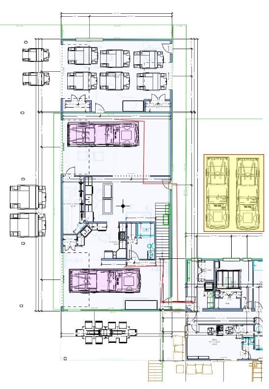
Everyday Parking
Purple boxes — where caretaker vehicles park day-to-day, inside the main garage bays, when the venue isn't hosting an event.
Event-Day Parking
Yellow boxes — a dedicated bay behind the event space where caretaker vehicles shift to when an event is underway, keeping the main floor clear for guests.
Walking Path
Red line — the caretaker's walking path from either parking position straight into the mud room entrance, without cutting through the kitchen or event floor.
This is a live working concept from Devon's CAD markup, not yet signed off by the structural team — brought to today's structural meeting for review. Moves to VIZ's official plan set and the Custer County permit path once confirmed.
These drawings are from the original concept when the shop was designed as part of the same structure as the caretaker house — an attached 2-car garage integrated into the TMOD modular unit. That approach has since been redesigned.
Current build (what's actually happening): Two separate structures — the TMOD factory-built modular caretaker house (two-box unit: Welcome Center side + 3bd/2ba caretaker side), and the Party Barn as a completely separate site-built structure with its own foundation, shop bays, event floor, and The Roost above. No attached garage. No shared roof. Two independent buildings.
Retained here for design history reference — like the original five-phase feasibility plan, these show where the vision started.
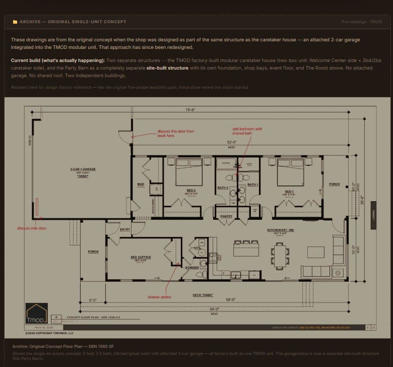
Archive: Original Concept Floor Plan — DEN 1560 SF (Annotated)
Shows the single-structure concept: 3 bed, 2.5 bath, kitchen/great room with attached 2-car garage — all factory-built as one TMOD unit. The garage/shop is now a separate site-built structure (the Party Barn). Red annotations mark open discussion items: the back door location, a proposed added bedroom with shared bath, the side door placement, and a shower addition — none of these are confirmed changes yet.
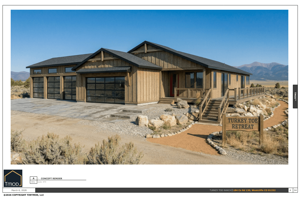
Archive: Original AI Concept Render
Shows shop bays attached to the caretaker residence — the original single-building concept. The actual build separates these entirely: TMOD modular house + site-built Party Barn are two distinct structures.
This is one physical TMOD factory-built structure split into two shared-use sides. For the check-in / retail side, see the Welcome Center page.